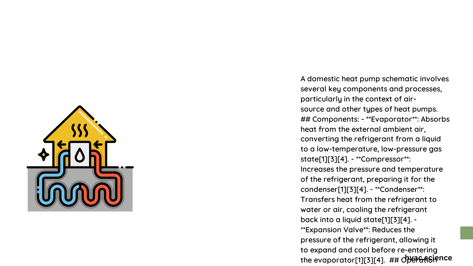
A domestic heat pump schematic represents a sophisticated thermal transfer system that efficiently moves heat from external environments into residential spaces. This intricate network of components transforms low-temperature energy sources like ambient air or ground into usable heating through precise refrigeration cycles, utilizing advanced thermodynamic principles to provide sustainable and cost-effective home temperature management.
What Are the Primary Components of a Domestic Heat Pump Schematic?
Core Mechanical Elements
Compressor Functionality
The compressor serves as the heart of the heat pump system, responsible for:
- Increasing refrigerant pressure
- Transforming low-pressure gas into high-temperature, high-pressure gas
- Driving the entire heat transfer mechanism
Compressor Specifications:
| Parameter | Typical Range |
|———–|—————|
| Power Consumption | 2-5 kW |
| Discharge Pressure | Up to 20 bar |
| Suction Pressure | Around 5 bar |
How Does Refrigerant Flow Through the System?
Refrigeration Cycle Stages
- Evaporation Stage
- Low-temperature refrigerant absorbs external heat
- Changes from liquid to low-pressure gas
-
Occurs at temperatures between -20 to 10°C
-
Compression Stage
- Refrigerant compressed to increase temperature and pressure
- Transforms into high-temperature, high-pressure gas
-
Typical efficiency ranges: 3-5 COP (Coefficient of Performance)
-
Condensation Stage
- Heat released from high-pressure gas
- Refrigerant condenses back into liquid state
-
Temperature range: 20-40°C
-
Expansion Stage
- Pressure dramatically reduced through expansion valve
- Refrigerant cools and prepares for next cycle
- Pressure drop: 5-10 bar
- Temperature drop: 10-20°C
What Electrical Considerations Exist?
Wiring and Power Requirements
Electrical Specifications:
– Power Supply: 230V single-phase or 400V three-phase
– Control Circuit Voltage: 24V
– Wire Gauges:
– Power Supply: 10-16 AWG
– Control Wires: 18-22 AWG
How to Install a Domestic Heat Pump?
Installation Best Practices
Required Tools:
– Drill
– Pipe cutter
– Wrenches
– Soldering equipment
– Electrical testing tools
Cost Estimates:
– System Materials: $3,000 – $10,000
– Installation Labor: $1,000 – $3,000
What Maintenance Challenges Exist?
Common System Issues
- External line freezing
- Refrigerant leakage
- Defrost mechanism failures
- Reduced operational efficiency
Performance Optimization Strategies
- Regular professional maintenance
- Proper insulation
- Optimal thermostat settings
- Annual system inspections
Conclusion

Domestic heat pump schematics represent complex yet efficient thermal management systems. Understanding their intricate design helps homeowners make informed decisions about sustainable heating technologies.
